

For some time now, I had the idea of building a clock made of 60 leds behind a milk-glass pane, showing the time with light.
Talking about this to some friends, I got the hint to search for the “Equinox Clock”.
And yes, I found it and was fascinated of this design mady by Bram Knaapen, see it here: Equinox Clock.
Unfortunately every detail in his great design exceeded our own ideas, so that we finally decided to build a clock copying his design, together with some fellow students.
(‘Copying’ is always such a bad word, but yeah its true.. 😉 )
So this will be a report showing how we rebuild something based on the images and videos shown here.
What did we do until now?
- Model creation and simulation
- Layouting the circuits
- Creation of the software
- Discussing materials (Todo)
- Final Result (Todo)
The current status is, that we left the draft phase of the circuits. I am writing the software for the microcontroller at the moment while assembling the PCBs at the same time.
More coming soon…
Simulation
Build up the clock in Pov-Ray to check how different materials fit together.
The PovRay scene-files have changeable parameters which can dynamically adjust the file to be rendered.
1st draft
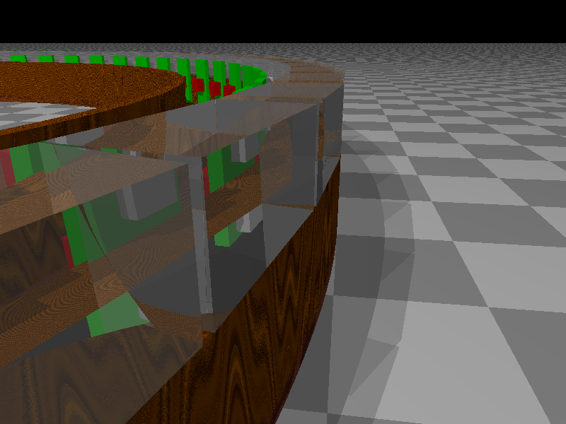
The main parameters for the first drafts were the dimensions of the clock, more specifically the inner and outer radius of the ring. All rendered objects which are dependent to these parameters are changed dynamically. The basic profile of the acrylic glass parts has been defined as 10mm x 10mm as these parts are commonly available. Another restriction of the ring-size emerges from the boards holding the RGB-LEDs so that the minimal required space per block is defined as 20mm in height and 10mm in width.
It turned out that the minimal outer radius should be higher than 200mm to get a pleasant appearance of the glass blocks.
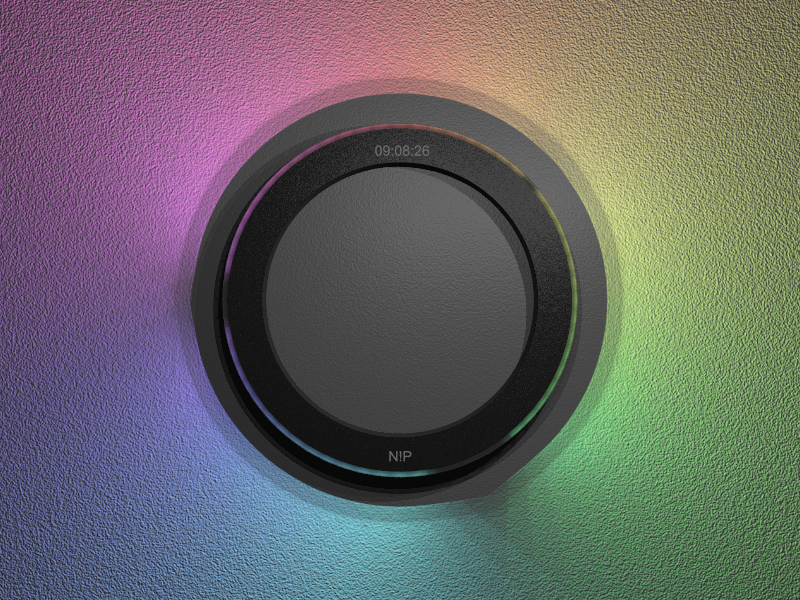
Adding the light

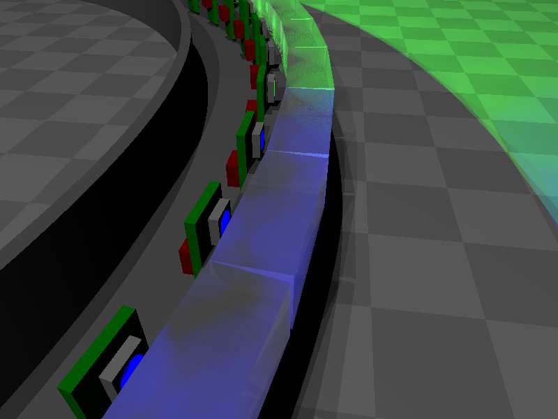
After the first draft of the clock’s body, the boards for the LEDs were added including fully configurable light sources for each element. This way the light can be set to different colour combinations and gradients. Adding some macros made it possible to retrieve different colour scenarios by simply changing some parameters. This step already required some layouting and electric component research in order to match the prospective appearance and behaviour of the components.
Refinements
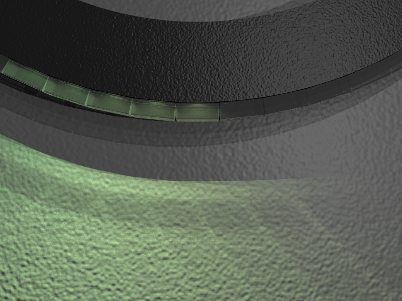
The effects of changing the parameters of the glass blocks were analysed as soon as the light sources were available. This resulted in variants with rectangular glass blocks and with a non-continuous ring. The breaks are important as the light of one light source would otherwise travel through large parts of the ring.
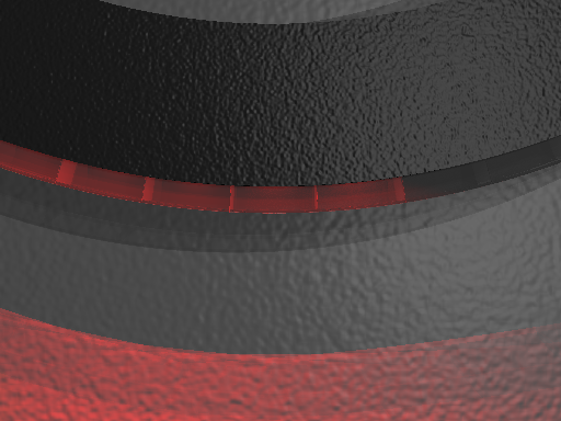
Adding the time
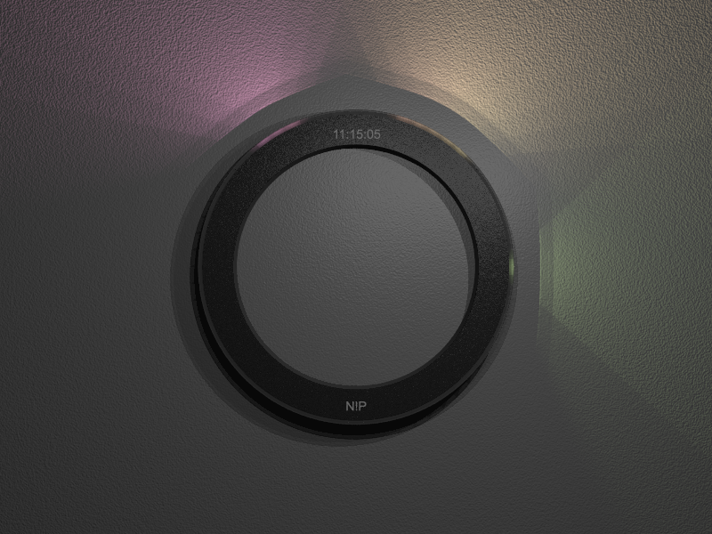
Another nice feature of PovRay which has already been used in small extracts is that the definitions language of the scene files is a programming language capable to solve complex tasks. The feature is applied to automatically generate a light signature for the time when the rendering process has been started. Also equipped with parameters, this macro helps to produce some nice-looking rendered images.
It looks as if the biggest effort has to be put into the assembly of the ring made of acrylic glass.
Variations
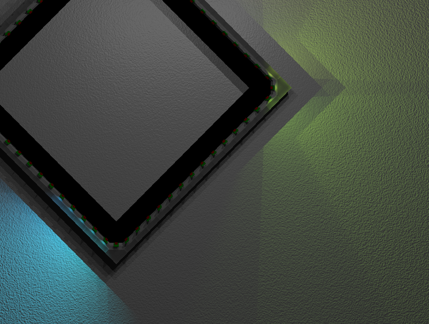
As we are working in a team, a second serious design proposal came up. The resulting form is an upright standing square.
This alternative offers on the one hand the possibility to dissociate from ‘just copying’ the original. On the other hand this design is easier to produce than a round shape.
A handicap of the square is, that the light is not distributed evenly around the object.
Layouting
The layout process consists of trying out different components available and lay out some circuits with it to check the resulting board sizes. The aim of this process is to get a circuit board which fits in the restricted space of the ring/square.
The work was done with the PCB-Design tool Eagle.
The result are 3 different kinds of PCBs, one for the LED assembly, one for LED driving and another one for the intelligence of the clock.
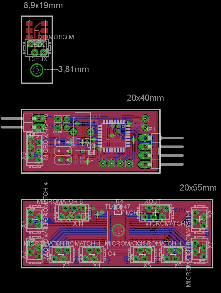
The first board just holds the LED at its place an is connected to the LED-driver by a short piece of ribbon cable.
The driver board contains a TLC5947 from Texas Instruments which is a 12-bit PWM constant current LED driver with 24 output channels, therefore able to drive 8 RGB-LEDs. 8 driver boards are daisychained by SPI to control all 60 RGB-LEDs.
The colour calculation is done by the ATMega328 on the controller board. Configuration and external control is done via serial uart connection.
The µC gets the time from a BQ3200 RTC-IC. The Real Time Clock is buffered by a SuperCap and should even survive some months without energy.
As I did non need all pins of the microcontroller, I made the spare ones available for later ideas.
First prototypes
I got my first few prototypes produced in tandem with some other PCBs and was really curious how good my first serious layout was.

After the first assembling and soldering, it turned out that the pads of the LEDs could be a bit bigger when using a soldering iron.
Additionally I had to notice that it will be impossible for me to solder the thermal pad of the LED driver as I forgot a hole in the middle of the PCB so I could heat the IC from it’s bottom side.
In the end, I didn’t even try to solder it as the IC seems to work anyway and the power dissipation of my design is not enough to overheat the LED-driver.
As a first test of my design, I wrote a small program which allows it to control the LEDs via UART connection. Voilà, it worked on the first onset, now I have a hand-adjustable mood-light! 🙂
Materials
Checking available materials and their prices. Wow. Maybe we should wait until we have a job! 😉
Software
The software for the clock is generally split in two different parts.
The first part is the clock mode:
The time will be read from the RTC-IC and the generated lighting values will be sent out to the driver-ICs.
The second part can be called remote mode:
In this mode it is possible to manipulate the configuration registers via UART and to write directly to the LED drivers. The protocol I built for this might not be revolutionary, but it does its job.